- Homepage
- About company
- Products
- Sales
- Service
- Press center
latest news :29.11.19
- Contacts


")


HMS Control L4-60 - Control & Protection Stations HMS Control L4


- Pumping EQUIPMENT
- Metallurgy, mining
- Food industry
- Firefighting
- Water intake
- Water supply
- Drainage
- Waste water
- Circulation
- Boiler water
- Water injection
- Water supply
- Water supply
- Circulation
- Boiler water
- Condensate removal
Function
Control & Protection Station (hereinafter referred as to the C&PS) «HMS Control L4» is designed to control and protect three-phase induction electric motors provided with squirrel-cage rotor, of foreign manufacture or domestically made; functionality is ensured by operator command or by sensor signal and it is suited to the requirements of Technical Specifications: 3432-112-00217975-2011.
C&PS "HMS Control L4" ensures the following design conditions:
- protection of three-phase induction motors:
- protection of electric motor against current overload/underload;
- protection of electric motor against phase loss, electrical imbalance or wrong phase sequence;
- protection of electric motor against increase/decrease of electrical line voltage;
- protection of electrical motor against body contact;
- protection of electric motors against overheating (temperature sensitive element of Pt100 type built-in motor , thermistor of PTC type (posistors) or thermal contacts);
- additional protection against overheat of the subassemblies of the pumping unit (up to 4 checkpoints);
- protection of electric motor and pump against "dry" running.
- automatic control over pumping units in the course of filling/discharging of liquids into the reservoirs – automatic maintaining of water level in the reservoirs;
- automatic dewatering of drainage pits through the instrumentality of the level gauges;
- the remote control over electric pumping units via wirelines (RS-485, Protocol ModbusRTU), the wireless control and monitoring via GSM channels or radio channel 433МHz, and the command-driven control from within SMS-messages;
- the single sensors with “dry” contacts, electric contact-making manometres (ECM) of any version, float switches, conductometric sensing elements (electrode sensors) and others digital sensing elements – may be used in the capacity of level gauges;
- it is possible to use the analog pressure-sensing elements or level detectors provided with unified current output of 4…20(0…20 mА);
- extended temperature range and too high level of dust-and-moisture protection; this makes it possible to use the station on open air;
- target function of site protection, furnished with signalling about unauthorized access (SMS-informing is possible).
C&PS corresponds to climatic version U2 or UXL4 as per GOST15150-69. (U2 – denotes operation in unheated premises or under the shed at a temperature of ambient air from minus 40 up to plus 40°С and relative humidity 100% at 25°С, UXL4 version – denotes operation in enclosed heated premises at a temperature of ambient air from plus 1 up to plus 40°С and relative humidity 80% at 25°С).
Level of protection of the C&PS against water and dust - IP 54 as per GOST 14254-96.
As far as the protecting people against electrical shock is concerned, C&PS is reffered to the 1st class, GOST 12.2.007.0 -75.
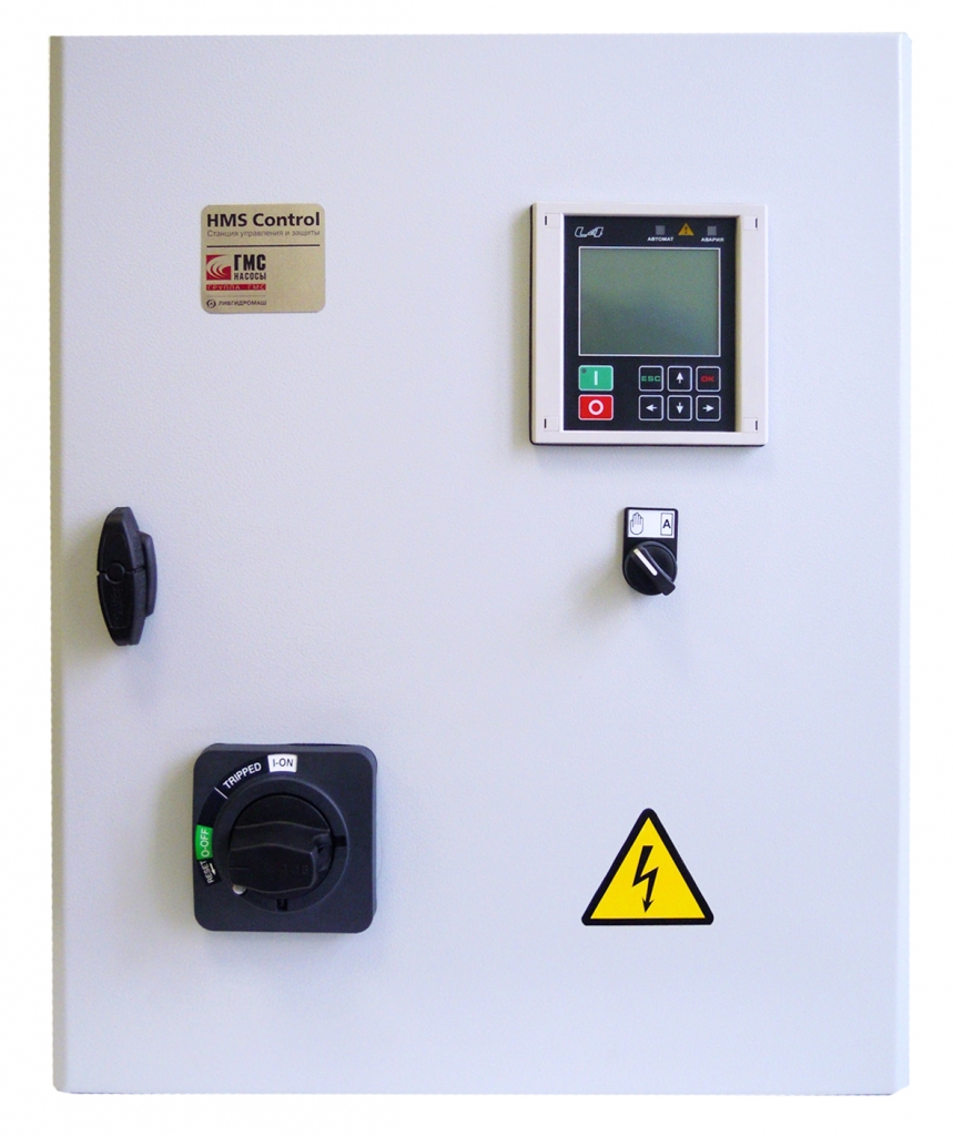
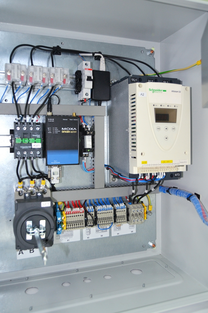
Design
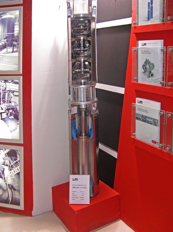
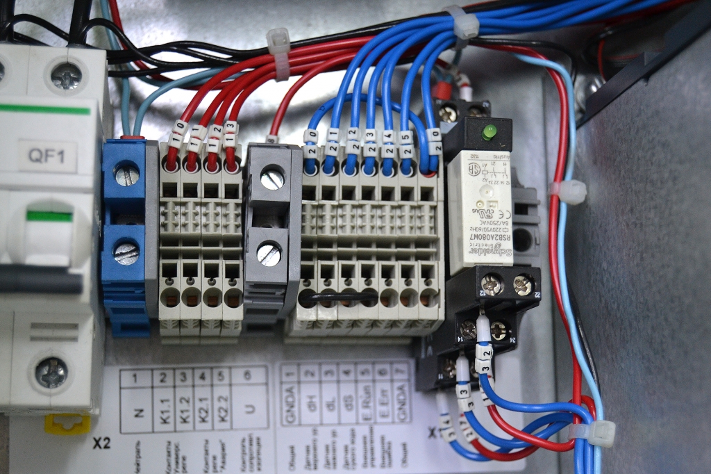
Control & Protection Station (C&PS) consists of the control board fitted with removable assembling panel, within which provision is made for automatic circuit breaker, electromagnetic starter, softstarter (depending on the version), electromagnetic relays (depending on the version), terminal blocks (power blocks and signal blocks) and current sensors (current transformers).
Arranged on the door of the control board is a microcontrolling device for control and protection -“L4" (hereinafter referred as to the MC).
Depending on the version, the station may include a switch-disconnector at the in-feeding port, monitor module for controlling the temperature of bearings of the motor and/or pump, protection module against impulse overvoltage (lighting protection) and GSM-modem of different modifications.
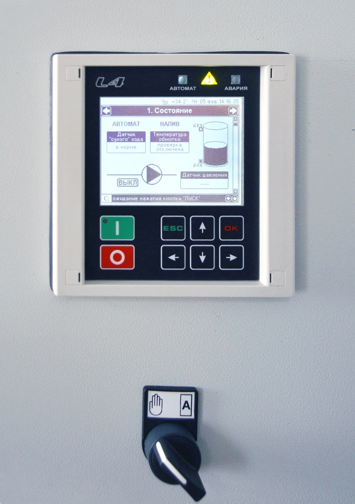
Arranged on the front panel of the MC (microcontroller) are the control buttons, namely: «START», «STOP», «OK», «ESC», navigation buttons, graphic LCD indicator and light-emitting diodes (LED) to indicate modes of operation and emergency conditions.
Arranged on the rear panel of MC casing are split-design terminals used to connect to the external electric power circuits and sensors.
The principle of operation of C&PS is based on processing the signals coming from external sources to the MC (microcontroller) and on operating the softstarter or the starter switching in/off the electric motor.
Provision is made for two modes of operation: manual operation, when the startup/stoppage of the motor is carried out by pressing buttons “START”/“STOP”, or automatic operation, when the startup/stoppage of the electric motor is carried out via the signal (s) from the level (pressure) sensor (s) or by the commands from APCS (Automatic Process Control System).
Application
- to ensure automatic control, monitoring and protection of the submersible/centrifugal pumps which are used at the water services plants, within Housing and Utilities infrastructure;
- to ensure control and operation of the submersible/centrifugal pumps working within the systems of water supply/water removal of the industrial plants;
- for agriculture purposes, in order to control and protect submersible/centrifugal pumps which are used within the systems of watering of the farmlands;
- within the systems of pressure boosting of the residential and industrial using activities;
- for the purposes of heat and power engineering, in order to operate, control and protect the submersible/centrifugal pumps used within the systems of process water supply;
- automatic dewatering of the drainage pit by using the level gauges;
- at the industrial productions, in order to ensure control, operation and protection of the subassemblies and mechanisms, in which good use is made of the three-phase induction electric motors.
Features /Advantages
- easy adjustment of modes of operation and parameters of protection;
- possibility to make corrections of the station settings in the course of operation without stopping the station (for example, readjustment of protection currents);
- possibility to represent discrete signals about station operation just on the supervisory keyboard (dispatching desk);
- light-emitting signalling about automatic mode of operation, motor condition and level of liquid in the reservoir (by signals fr om the sensing elements);
- possibility of pre-alarm signalling in order to prevent accidents at the earliest time;
- track of operating time and record keeping of engine starts of the pump in order to perform well-timed technical maintenance;
- adjustable quantity lim it for engine starts of the electric motor of the pump;
- possibility of cascaded operation of several stations to suit one storage tank or main line;
- additional inputs «External control» and «Outward breakage»: thus allowing to operate the station remotely and to stop its operation under outward emergency conditions;
- calculation of working values of the currents and voltages (TrueRMS) for every phase and their representation (displaying) on the LCD display;
- additional modes of operation (timers of launch delay, stop action, emergency shutdown and other timers);
- automatic restart of the motor after operating trouble or after loss of electric power supply of the station;
- possibility to operate the station remotely via wirelines and wireless links, as well as by means of sms-messages;
- galvanic isolation from the mains of all sensors' circuits within the microcontroller, thus excluding injury by current of the attending personnel;
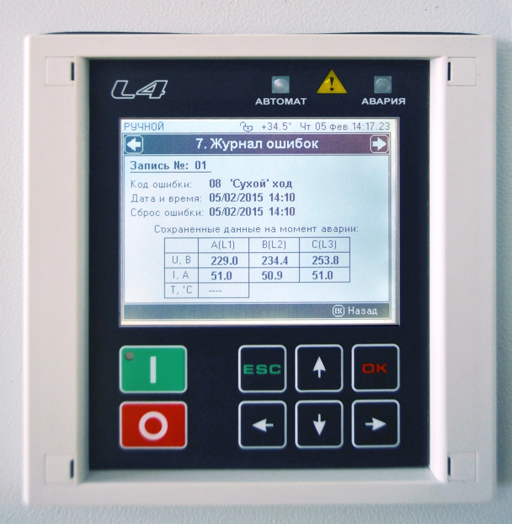
- availability of the alarm history in the memory of the MC together with an indication of emergencies' time, current and voltage values, and the temperature at the moment of operating trouble;
- adjustment of the station does not require additional equipment and it is easy to be serviced by low-skilled personnel;
- it has been certified for use within the Customs Union.
Technical parameters
| Options | Values |
| Series | HMS Control L4 |
| Weight, kg | 26 |
Pump type key
For example HMS Control L4-25-P-M-IP54-UXL4 , where :
- HMS Control L4 - is the name of the station
- 25 – is the maximum permissible rated current of the electric motor to be connected up, А
- P – mode of startup of the pump: P – soft start, without index number - direct starting
- М – additional functions (if they are not available - not to be indicated):
- R – switch-disconnector at the input port
- М – protection against impulse overvoltage
- GPRS – data transfer and control via the GPRS-channel of cellular communications
- SMS – control and monitoring over operation of the station with the help of short text SMS-messages
- T2 – temperature control of the bearing assemblies of the pump (2 sensors)
- Т4 – temperature control of the bearing assemblies of the pump and motor (4 sensors)
- E – potential for use of electronic level gauges
- O – heating-up of the control cabinet (climatic version U2)
- IP54 – Degree of protection of enclosure as per GOST 14254-96
- UXL4 – Climatic version and location category
Main specifications.
|
Denomination |
Parameter |
|
Rated supply voltage, V /current frequency, Hz |
~380/50 |
|
Quantity of in-feeds, pcs. |
1 |
|
Permissible deviation of the supply voltage fr om the rated value, % |
+10
|
|
Maximum current of the electric motor to be connected up, А
|
300 |
|
Range of temperature during operation, °С |
+1…+40 (-40…+40 for U2) |
|
Degree of protection of enclosure as per GOST 14254-80 |
IP54 |
|
Normal power feeder, inputs for electric motor and sensors |
in the bottom portion of the cabinet |
|
Kind of climatic version |
UXL4 (У2) |
Input signals of the control cabinet.
|
Denomination of the input signal |
Kind of signal |
|
Sensor of “dry” running 1 |
= 24V |
|
Sensor of “dry” running 2 | |
|
Sensor of lower level | |
|
Sensor of upper level | |
|
Sensor (line loop) of the burglar alarm | |
|
«External» control | |
|
«External» error | |
|
Signal «Automatic mode of operation» | |
|
Analog pressure/level sensors |
4…20 (0…20) mА |
|
Temperature sensor (Pt100, RTS, thermocontact) |
0…3,5 кOhm |
|
Current sensor 1…3 |
0…5 А |
|
RS-485 |
= 5V |
|
RS-232 |
= 12V |
Output signals of the control cabinet.
|
Denomination of the output signal |
Characteristcs |
|
Operating trouble (emergencies) |
НО/НЗ relay contacts
|
|
Custom event (to be adjusted by the User)
|
HMS Control L4 ensures operation of the pump in the following modes of working:
- «Manual operation» - the pump motor is activated by buttons on the frontal panel of the controller;
- «Automatic operation» - control is effected by way of a signal coming from the pressure/level sensor(s).
- by commands from the PC (PLC) via wirelines or wireless communication links
- by commands from sms-messages
In automatic mode of operation the HMS Control L4 ensures the following main functions:
- filling/discharge of the reservoirs according to signals coming from discrete level sensors of different type (electrode sensors, electric-contact manometers, float sensors and so on);
- filling/discharge of the reservoirs in response to a timer and in according to one of the level gauges (timer value from 1 up to 180 minutes);
- filling/discharge of the reservoirs according to the pressure relay;
- filling/discharge of the reservoir according to the analog pressure-sensing element of 4…20 (0…20) mА;
- remote switching on/off of the station motor in response to an external control signal;
- remote switching on/off of the station motor by commands coming from the remote PC (PLC);
- remote switching on/off of the station motor by commands coming from sms-messages.
HMS Control L4 ensures protection in the following situations:
- «dry» running (when good use is made of the corresponding sensor (s);
- overload of the motor - – to be adjusted by the User within the range of 1…300 А;
- underload of the motor (protection against «dry» running without additional sensor) – to be adjusted by the User within the range of 0,5…299 А;
- wrong sequence or absence of input phases (to be checked during switching-on);
- too high or too low supply voltage –to be adjusted by the User within the range of 180…245 V;
- phase loss/electrical imbalance;
- failure action of the level gauges (level detectors) (under automatic operation conditions);
- malfunction of the analog pressure/level sensor;
- overheating of the motor or temperature sensor problem;
- too great number of motor starts per an hour;
- too low insulation resistance of the electric motor – less than 15 кOhm.
Manual mode of operation

Manual mode of operation is intended for local control of the motor in the course of assembly and service activities. The proper motor switching in/off is effected by depressing the buttons «Start»/«Stop», arranged on the frontal panel of the MC. Transition to the manual mode of operation takes place when the flag indicator SB1 is moved into the position «Manual».
With the unit being operated manually, all the protective gears (protections) are actuated but with the exception for control of correct operation of the level indicators and limitation on number of motor starts per an hour. When the protective gear is actuated the motor is to switch off and the blinking inscription about emergency situation together with the sound signal is displayed before the operator intervention.
Time timers of duration of work and the switch on/ switch off time timers are not used.
Remote motor control via communications lines or sms-messages is blocked.
Automatic mode of operation according to the level gauges
Under automatic operation conditions the pump motor is automatically switched on/off according to the discrete or analog pressure/level sensors. Depending on the station function that is to be chosen by the User it is possible to maintain automatically the water level in the reservoir or to drain the drainage pits.
«Filling» Control Function
When the liquid column is lowered below the low-level indicator, the supply mains and motor are checked for condition and the signal of the sensors is verified for correctness. Thereupon the actuation of the pump motor takes place. In the course of filling process the control of currents and voltages is constantly carried out, those values are to be within the set limits. If the current and voltage values go beyond the target values' range during the prescribed time period, the electric motor is subject to emergency shutdown. In such a case the indicator will display the code of the offered error and the time up to the next following launch of the motor. Additionally in the course of operation the status of the input “External control” and the condition of the “dry” run sensor are to be verified. When the reservoir is filled up till the upper level, the motor is switched off and the MC (microcontroller) is moved to the drainage waiting mode.
Under automatic operation conditions the status of the level gauges' contacts is always controlled..
As the problem connected with wrong functioning of the sensor contacts appears (for example, the high-level indicator is actuated prior to the low-level indicator), the level LEDs start flashing and in 2 minutes the protective gear is activated. The motor is switched off and the blinking emergency code is displayed. The error is cleared just after regeneration of signals coming from the sensors (indicators).
Some additional functions are available during automatic operation, namely: emergency shutdown timer and on and off delay-make timer.
The emergency shutdown timer is designed to exclude the overfilling due to fault of one of the level gauges (for example, the high-level indicators at the water tower are frequently frozen). The task of the timer – to de-energize the motor on expiration of time period prescribed in the setup menu (in minutes), if the high-level indicator did not come into action. The timer is initiated together with the motor actuation during filling process and it is reset to zero when the motor is switched off. If the level gauge operates prior to the timer (with respect to time), so the timer is stopped up to the next following motor activation. After timer-clock response and on expiration of restart time after emergencies, the operation of the station is to be continued as per normal, the Microcontroller looks forward to lowering of the liquid level.
On & Off delay-make timers make it possible to ignore false level signals under possible water hammer effects on the long lines, which are involved just after motor switching in/off. The start-up command or the stop command of the motor will be executed only after stabilization of the pressure jump and stable condition of the sensor contacts during time period predetermined by the User. In addition, one should use delay timers in order to organize the group (cascade) mode of operation for several pumps just to suit one storage tank or drainage tank with common level gauges. Switch on/ switch off time of every station from the group is adjusted in dependence to operation conditions for a time period up to 180 seconds.
«Drainage» Control Function
Operation of the station under drainage conditions is identical to operation under filling-up conditions with the exception of reverse sequence of motor switching in/off when the liquid level is changed. When the liquid comes up to the upper level, the motor is just actuated. When the minimum level has been reached, the motor is stopped, in such a case the station will be looking forward to filling-up of the reservoir up to the upper level. Similar to above-mentioned filling-up function, it is possible to use the following functions, namely: switch on/switch off delay and emergency shutdown function as well.
As far as the “drainage” control function is considered, bear in mind that the launch time delay and the shutdown delay functions are in analogy with the station function of “filling process”, but the timer of emergency shutdown is activated jointly with the motor and is cleared when the lower level is reached.
Automatic mode of operation according to the timer-clock and the upper (lower) level indicators.
The said mode of operation is provided for such conditions when the installation of the high-level sensor (indicator) is not really possible (for example, the high-level sensors which are used at the water towers are to be covered with ice during hard frosts and as a result they become non-operative), and the electric-contact manometer has difficulty in use for some reason. In this case only one level indicator is to be installed; after its triggering the filling-up/drainage of the reservoir is effected during time lim it required for the purpose of filling and draining. The high-level sensor (indicator) is not used during automatic mode of operation. The filling function or drainage function is to be chosen in the setup menu of the microcontroller (MC). In the course of filling-up process the good use is made of the low-level sensor input, during drainage – the input of high-level sensor is brought into operation.
In the process of filling
If the sensor is found in open position, it means that the liquid is not present in the reservoir, so the pump motor starts working for a time ranging from 1 up to 180 minutes (time to be changed by the User in the setup menu). The time for filling a specific tank is selected by way of trials in hand-operated regime. When the time of filling is expired the MC will look forward to opening operation of the low-level indicator and then it will repeat over again the cycles of filling.
In the process of drainage
If the sensor is in closed condition, it means that reservoir has been filled up, so the motor starts working for a time ranging from 1 up to 180 minutes. Time required for draining the certain reservoir is chosen manually by trial. When the time of bleeding (draining) is expired, the MC will look forward to closing operation of the low-level sensor, иand then it will repeat over again the cycles of drainage.
As in all other modes of operation, the check-up of all applied protective parameters is carried out just before the start and in the course of the electric motor operation.
Remote discrete control over motor operation
Remote control is possible with the help of the input “External control” of the station. The said input must be enabled in the setup menu of the MC. Under automatic operation conditions the closure of the said input admits operation of the station in this mode of functioning, the opening (breaking) of the said input – forbids the operation. The motor is to be switched on just while the level gauges will operate with positive action in accordance with applied duty cycle and function. Restart after emergency condition will take place after the expiry of the prescribed hold-up time.
During manual operation at closing of the input, the electric motor is energized immediately, at opening of the input – it is de-energized. After actuation of the protective gear the motor is to be switched off and the blinking code of emergency will be kept on the indicator. The alarm clearance and restart in case of enabled input «External control» - the opening of the said input or the depressing the «Stop» button of the MC. The emergency condition will be cleared and, in dependence to input status, the motor will be switched in/off.
In the time of activated «External control” input, the buttons «Start» and «Stop» of the Microcontroller will be blocked.
Remote control and monitoring of the station
The said operation is provided to control remotely the motor via the wirelines or wireless communication links. L4 is furnished with physical interfaces RS-485 and RS-232, by which it is possible control remotely and to monitor all the parameters of the Microcontroller. The specific port is chosen by the User in the setup menu. The communication ptotocol with remote PC or PLC - ModbusRTU. The transmit speed of 2400...57600 bit/sec., the length of communication line (tie line) – up to 1 km. (suits for RS-485). In case of longer communication lines it is necessary to use the repeaters or radio modems.
Under such mode of operation the managing program (supervisory program) for PC (PLC) or the User read the L4 sensors' status or the decision about switching in/off the motor is made at own discretion. The motor is switched in/off by writing “1” or “0” into the zero bit of the register “Control”. The working status of the sensor (s) of “dry” run is constantly checked just after the supply power-on with no regard to the mode of operation. The duty of the station (filling or drainage) and the type of the level gauges does not have an effect on motor operation, their condition is printed on the screen. The switch in (switch off) delay-make timers and emergency shutdown timers are not used under given working conditions. When the protective gear operates with positive action the motor is switched off and the error message is screened on the indicator. The error is automatically reset just after the expiry of hold-up time or after having performed the forced clearance from the PC (PLC). Under such operation conditions the User controls the general-purpose relays 1 and 2 (K2 and К3) by way of the remote PC or PLC. Their functions, chosen in the setup menu, ARE TRIPPED OFF! The relay is switched in/off by writing the 1(0) value into the corresponding bites of the Register “Control”, described in the document “L4. Protocol specification Modbus RTU”.
If the wirelines are not available, the monitoring and control over the station may be effected with the aid of radio and GSM-modems. The modems may be connected to not only to interface RS-485, but also to RS-232(to be adjusted in the setup menu L4).
The both GSM-modems (one modem within the control box of HMS Control L4, but the second – in CPCS (Computerized Process Control System) are automatically interconnected and exchange data via the Protocol Modbus RTU. In case of radio modems it is necessary to adjust the communications parameters of both modems only, for the case with GSM-modems the sim-card of the station modem must be provided with constant (static) IP-address and data communication function (to be provided by the cellular communication operator). With supply power-on the GSM-modem of the station is Online registered with constant address, and expects for requests from the CPCS modem. The CPCS of the User with the help of the second GSM-modem transmits requests to pre-existing IP-address of the station modem and receives data from the latter.
It is possible to switch in/off the motor by way of commands from the sms-messages.
The operating principle: the User sends the sms from the cellular telephone to the number of the GSM-modem with certain control command. The GSM-modem receives the said message and transmits it to the L4, the latter is to analyze the message and to start/stop the pump motor. During processing of the command the number of the phone with whom the above-mentioned message was sent is verified without fail. If the number of the phone does not coincide with the number prescribed in the L4 setup menu, the said message will be ignored. It is done in order to exclude attempts of unauthorized control of L4 from another phone numbers.
Supposedly, the following working situations might be expected when in connection with equipment failures or because of the unstable operation of the cellular network the User can run out of control over operation of the pump, and as a result of which, for example, the overflow of the reservoir and the flooding of the premises or working site will take place. To exclude such cases and situations the L4 has provision for emergency shutdown of the pump motor within the target time to be preset by the User. Besides, at the moment of receiving the message provided with the command, the proper time of message delivery is to be verified. In consequence of possible faults (upset conditions) or due to great workload of the cellular communication operator, the message with the control command may be delivered with great. In order to exclude undesirable startup/stoppage of the motor in such cases, during processing of the accepted message the L4 is to check the delivery time of the said message. If the time-delay is more than 15 minutes the given command is ignored, and the reply message with indication about time-delay will be sent.
Distance transmission of operative signals
For distance transmission of the signals to the dispatcher desk or CPCS (computerized process control system) provision is made in the station for three electromagnetic relay K1-K3 of the controller provided with double-throw contact.
The relay К1 is adjusted to operate with positive action under emergency situation. As for the relay К2-К3 the closure of the relay contacts takes place in dependence to selected condition within special item of the MC setup menu.
Available are the following variants of relay actuation:
- operation of the station (power is supplied);
- emergencies of the station;
- switched in/off motor;
- input condition «External error»;
- input condition «External control»;
- input condition «High-level indicator»;
- input condition «Low-level indicator»;
- input condition «Sensor 1 of “dry” running»;
- input condition « Sensor 2 of “dry” running »:
- pre-emergency situation
- activation of the protective signaling.
In case of necessity, the signal «Switched on/off motor» may be obtained by using additional NО-contact (a-contact) which is accommodated within the electric contactor.
To be more familiar with the operation of the station refer to the documents «L4 Programming Manual», «HMS Control L4 Operation Manual » and «L4. Protocol Specification C Modbus RTU».
The use of different types of level sensors
 |  |
 |  |
 |  |
 |  |
 |  |
|
|
|
Instruction manual :
All technical documentation in the Russian version of the site »
Certificates, permits :
All certificates, permits in the Russian version of the site »