PRODUCTION AND SALE
| Sale of pumps: | sbyt@hms-livgidromash.ru |
|
Reception: |
lgm@hms-livgidromash.ru |
- Homepage
- About company
- Products
- Sales
- Service
- Press center
latest news :29.11.19
- Contacts


")


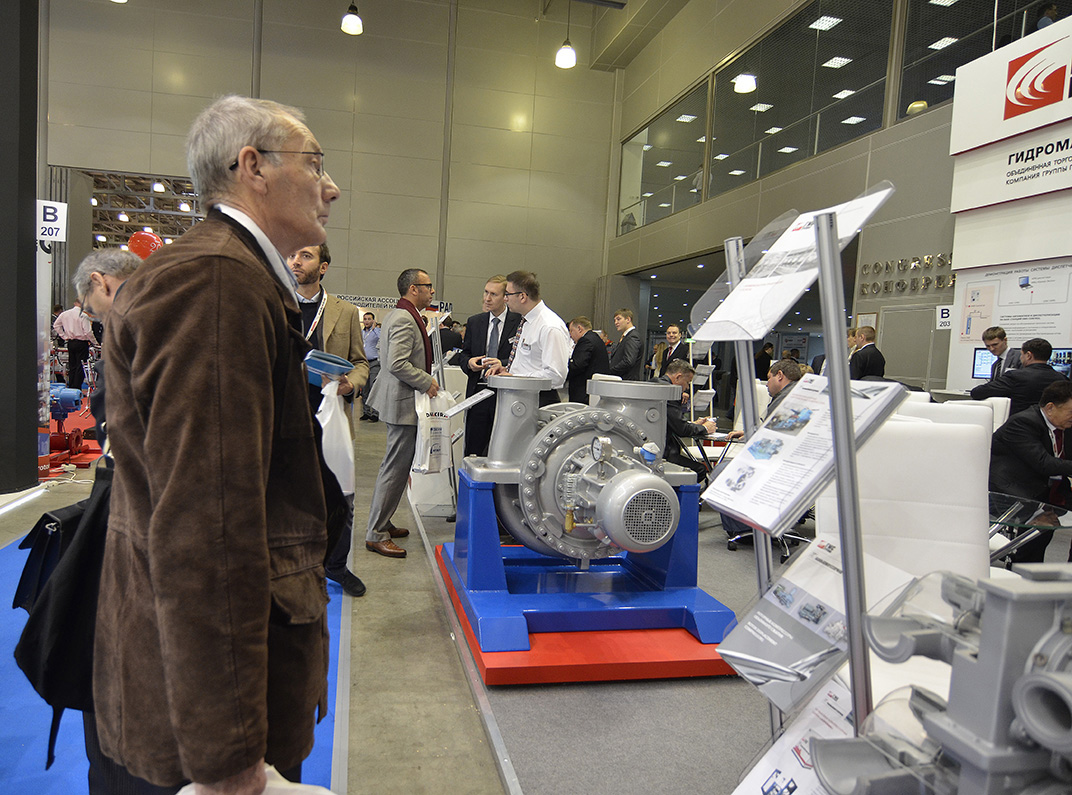
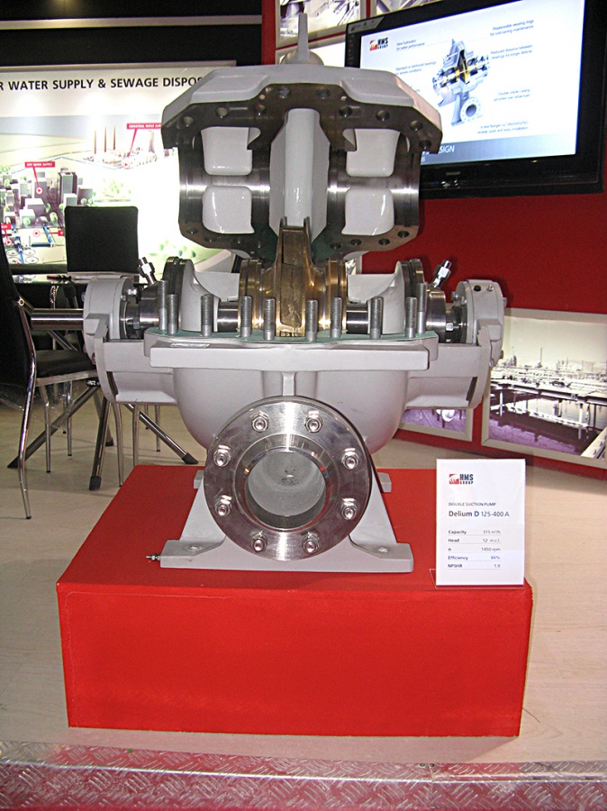


Centrifugal double-suction pumps D

- Double-suction
- Nuclear power
- Metallurgy, mining
- Firefighting
- Water intake
- Water supply
- Water injection
- Water supply
- Water supply
- Chemically active
- Clear water
- Brine water
- Sea water
- Hot water
- water + petroleum products
Function
Centrifugal double-suction pumps D,1D,2D are designed for handling water and chemically active non-toxic liquids having a density up to 1100kg/m3, at a viscosity up to 60*10-6 m2/s (60sSt), at a temperature up to 368К (95°С), with a content of solid inclusions not exceeding 0,05% by mass and not exceeding 0,2 mm in size, at micro-hardness not exceeding 6,5 GPа (650kgf/mm2).
The pumps are referred to the items of general-purpose, aspect I (repairable ones) GOST 27.003-90.
The pumps and units are manufactured in climatic version and location category UHL 3.1, У2 and Т2 as per GOST 15150-69.
Pumps and units are supplied for export as per OST 26-06-2011-79.
The pumps and units are designed for the regions with seismic activity up to 7- points inclusive on the MSK-64 seismic scale.
The pumps and units are made in compliance with the general safety standards as per GOST R 52743-2007.
The pump units with the pumps having an embodiment index «Е» and furnished with explosion-proof electric motors may be used in explosion-and-fire hazard productions within the zones of 1 and 2 class GOST R 51330.9-99.
Design
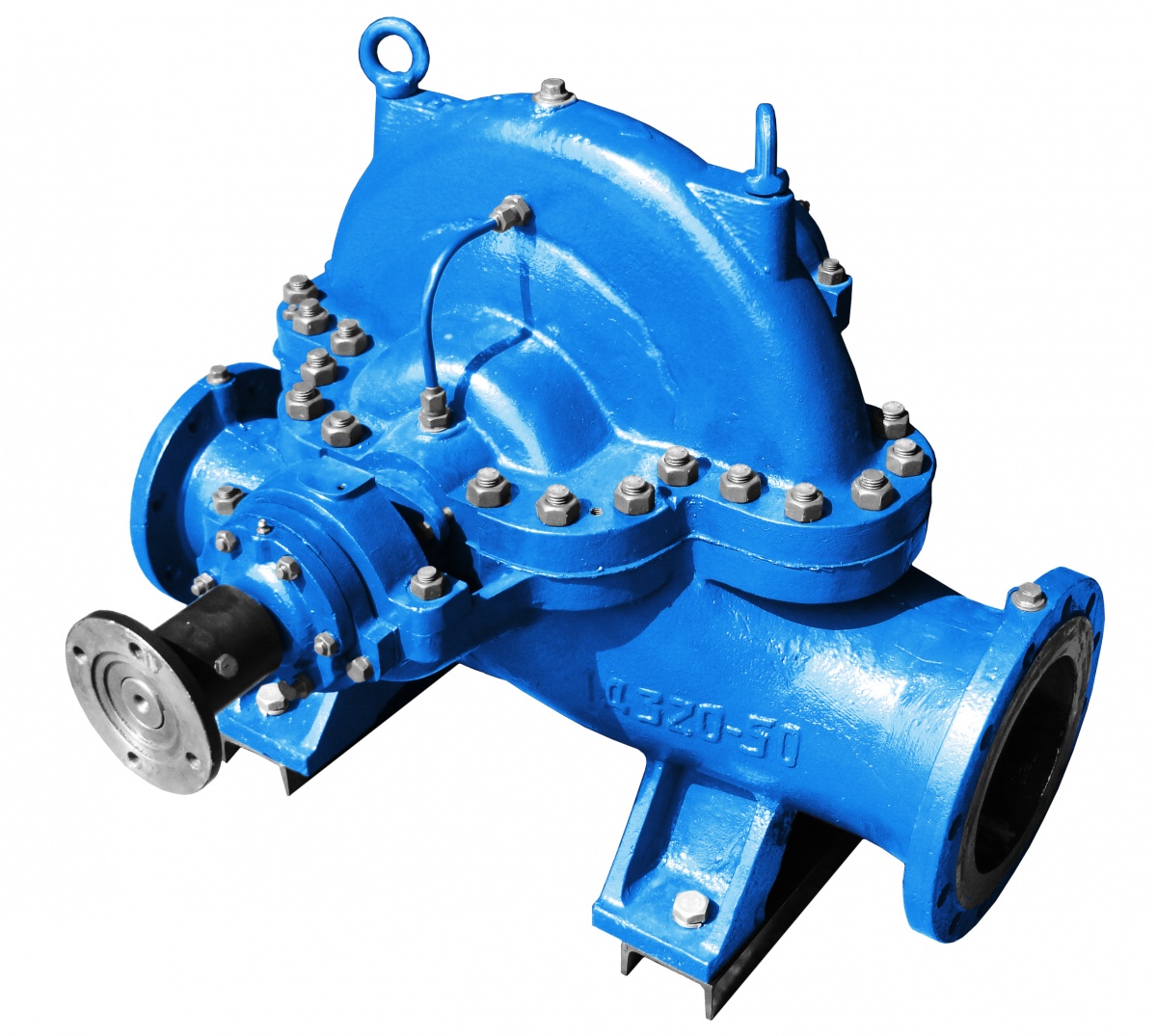
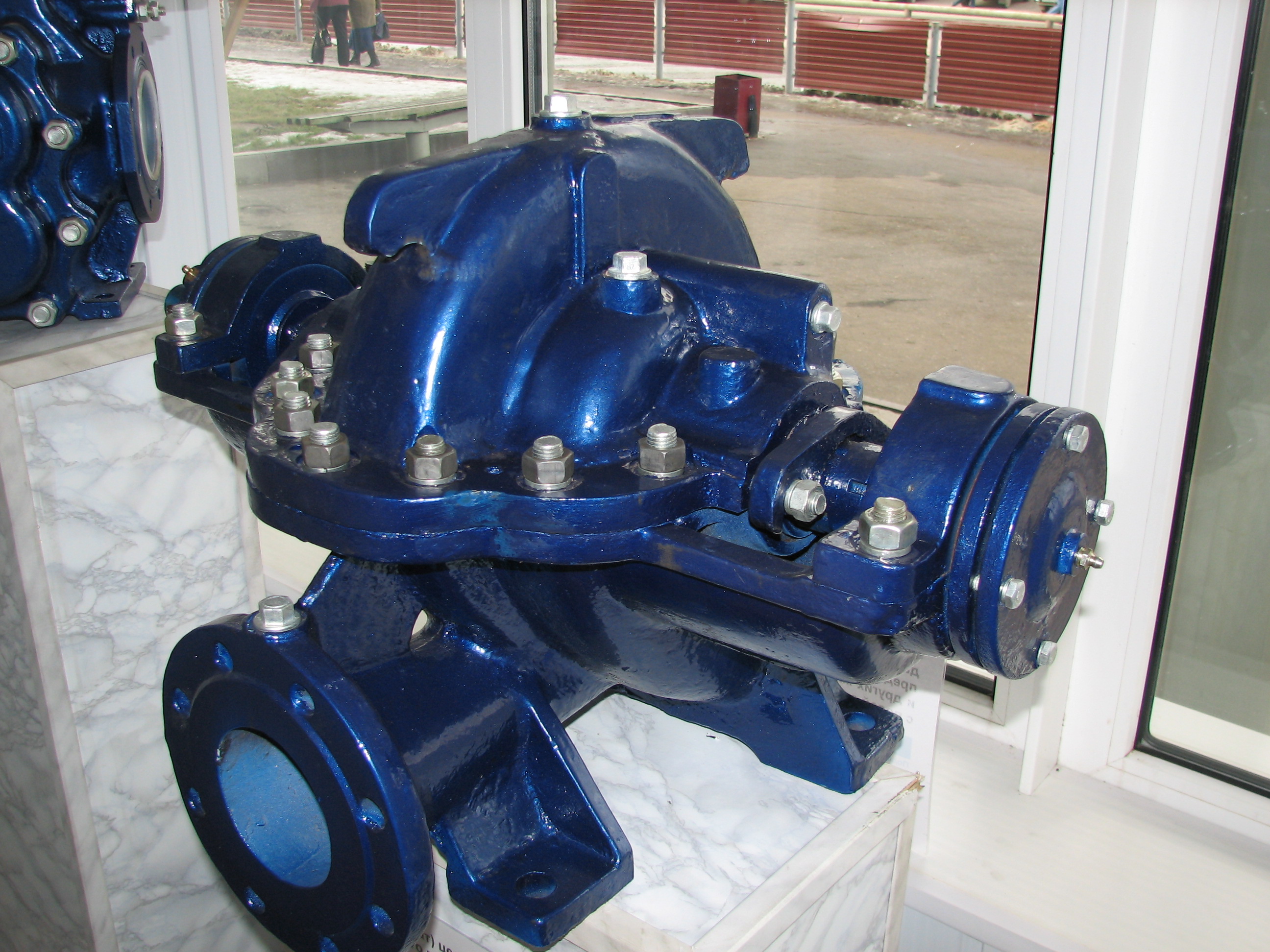
D,1D,2D series are centrifugal, double suction, horizontal single-stage pumps with double-sided semi-volute supply of liquid to the impeller of double-suction and with volute discharge.
The principle of operation consists in transformation of mechanical power of the drive into the hydraulic energy of the liquid due to hydrodynamic influence of the impeller blades, suction & discharge nozzles.
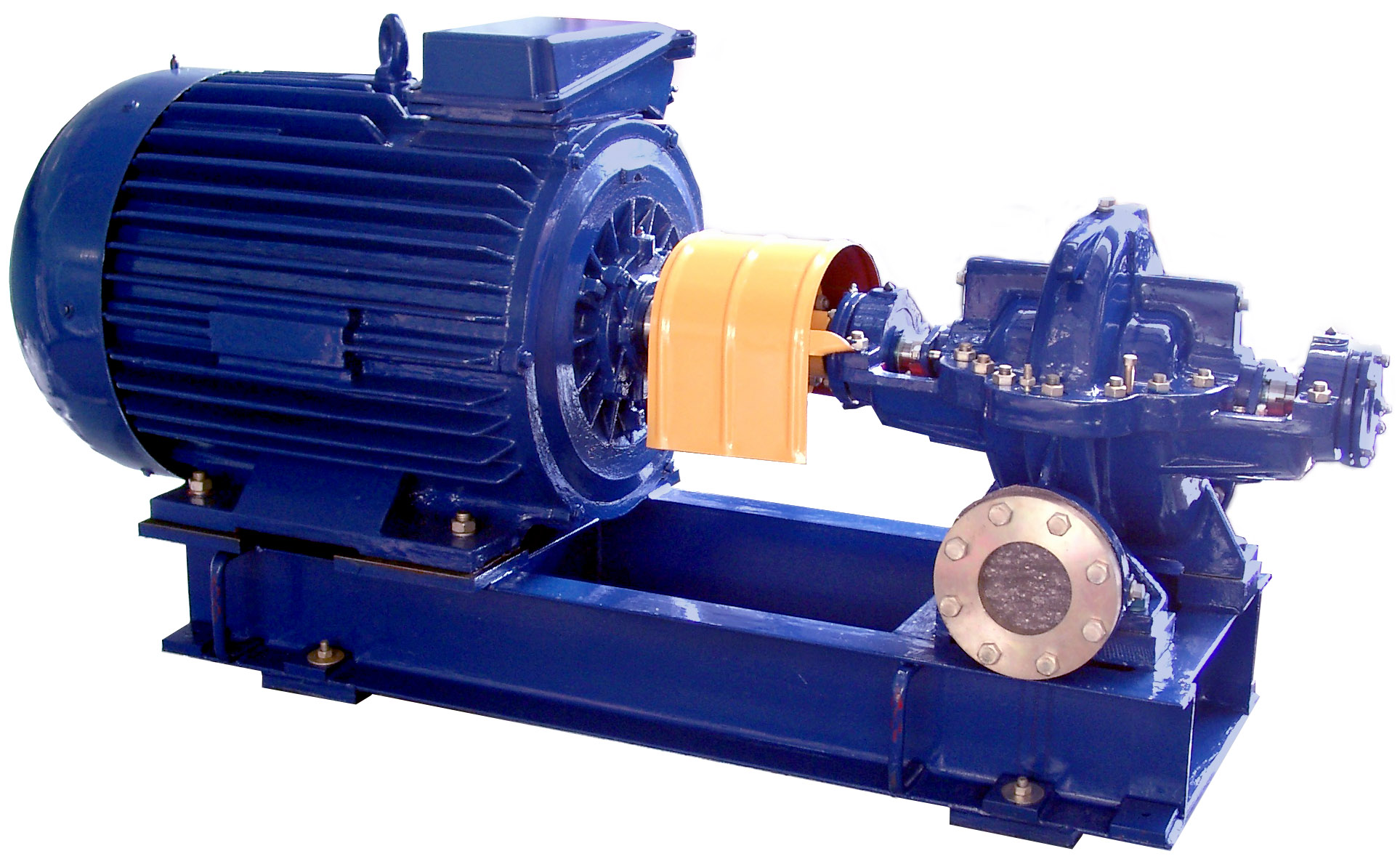
The electric pump unit consists of a pump and driving motor, mounted on a common welded baseplate and connected coupling.
The pump case is an iron or steel casting, which has a joint in the horizontal plane passing through the axis of the rotor.
The suction and discharge branch pipes of the pump are positioned in the bottom part of the case and are turned in different directions, owing to which the pump may be disassembled and repaired without disconnecting the pipelines and removing the electric motor.
Mounting dimensions of the flanges of the suction and discharge branch pipes are made acc. to GOST 12815-80 (version 1). At the Customer's request it is admitted to apply version 3 GOST 12815-80 for the said flanges.
The case cover extends the configuration of the passages of the case .In the top portion of the case cover there is a hole М16х1,5, closed with plug and used for connecting a vacuum pump or for linking up a vacuum treatment system, as well as for releasing the air when the pump is filled up “by gravity”.
The sense of rotation of the rotor is left-handed (counterclockwise), as viewed from the drive end. At the Customer's request it is possible to manufacture the pump with right-handed rotation of the rotor (clockwise).
Impeller – is the double-entry one: thus it allows to place the axial forces in certain equilibrium. The remaining axial forces are taken up by the radial or radial-thrust ball bearings.
To prevent leakage of liquid along the shaft provision is made in the pump case for the gland seals or for the single end-face seals.
Application
- water-supply/heat supply
- water intake
- water supply in oil fields
- sea water supply for firefighting systems in sea port infrastructure
- handling of water with oil product traces in oil-production and processing
- handling of water and similar liquids in chemical processing
- handling of service water in heat supply, including nuclear power plants
- cooling systems in metallurgy
- industrial and civil firefighting systems, including diesel driven pump units
Features /Advantages
- extensive list of material selection provides pumps for any application
- wide range of impeller diameters and their customization provide the most optimal selection for the client
- double suction impeller absorbs axial thrust to lowerbearing load
- double volute casing reduces the radial load on the shaft
- axial split casing provides maintenance without pipeline dismantling
Technical parameters
| Pump models | Flow (nomin.), m³/h | Head, m | Pump power input (max.), kW | Rotation speed, rpm | Rotation speed, c˜¹ |
| D 160-112m | 160 | 122 | 92 | 2900 | 48.3 |
| D 160-112 | 160 | 112 | 86 | 2900 | 48.3 |
| D 160-11a | 140 | 100 | 75 | 2900 | 48.3 |
| D 160-112b | 135 | 80 | 53 | 2900 | 48.3 |
| D 160-112m | 90 | 30 | 13 | 1450 | 24.2 |
| D 160-112 | 80 | 28 | 12 | 1450 | 24.2 |
| D 160-112a | 75 | 25 | 10.5 | 1450 | 24.2 |
| D 160-112b | 70 | 21 | 8 | 1450 | 24.2 |
| D 200-36 | 200 | 36 | 35 | 1450 | 24.2 |
| D 200-36a | 190 | 30 | 27 | 1450 | 24.2 |
| D 200-36b | 180 | 25 | 21.5 | 1450 | 24.2 |
| D 320-50 | 320 | 50 | 68 | 1450 | 24.2 |
| D 320-50a | 300 | 39 | 48 | 1450 | 24.2 |
| D 320-50b | 300 | 30 | 35 | 1450 | 24.2 |
| 1D 200-90 | 200 | 90 | 80 | 2900 | 48.3 |
| 1D 200-90a | 180 | 74 | 60 | 2900 | 48.3 |
| 1D 200-90b | 160 | 62 | 44 | 2900 | 48.3 |
| 1D 200-90 | 100 | 22.5 | 12.5 | 1450 | 24.2 |
| 1D 200-90a | 90 | 19 | 10.5 | 1450 | 24.2 |
| 1D 200-90b | 80 | 16 | 9.5 | 1450 | 24.2 |
| 1D 250-125 | 250 | 125 | 131 | 2900 | 48.3 |
| 1D 250-125a | 240 | 110 | 105 | 2900 | 48.3 |
| 1D 250-125b | 220 | 90 | 92 | 2900 | 48.3 |
| 1D 250-125 | 125 | 30 | 18.5 | 1450 | 24.2 |
| 1D 250-125a | 120 | 27.5 | 16.5 | 1450 | 24.2 |
| 1D 250-125b | 110 | 22 | 12.5 | 1450 | 24.2 |
| 1D 315-50 | 315 | 50 | 62 | 2900 | 48.3 |
| 1D 315-50a | 300 | 42 | 46 | 2900 | 48.3 |
| 1D 315-50b | 220 | 36 | 36 | 2900 | 48.3 |
| 1D 315-71 | 315 | 71 | 87 | 2900 | 48.3 |
| 1D 315-71a | 300 | 62 | 72 | 2900 | 48.3 |
| 1D 315-71b | 280 | 52 | 65 | 2900 | 48.3 |
| 1D 315-71 | 160 | 18 | 15 | 1450 | 24.2 |
| 1D 315-71a | 150 | 17 | 14 | 1450 | 24.2 |
| 1D 315-71b | 130 | 14 | 11.5 | 1450 | 24.2 |
| 1D 500-63 | 500 | 63 | 130 | 1450 | 24.2 |
| 1D 500-63a | 450 | 53 | 97 | 1450 | 24.2 |
| 1D 500-63b | 400 | 44 | 72 | 1450 | 24.2 |
| 1D 500-63 | 340 | 28 | 41 | 980 | 16.3 |
| 1D 500-63a | 300 | 24 | 34 | 980 | 16.3 |
| 1D 500-63b | 270 | 20 | 24 | 980 | 16.3 |
| 1D 630-90 | 630 | 90 | 230 | 1450 | 24.2 |
| 1D 630-90a | 550 | 74 | 192 | 1450 | 24.2 |
| 1D 630-90b | 500 | 60 | 130 | 1450 | 24.2 |
| 1D 630-90 | 500 | 38 | 84 | 980 | 16.3 |
| 1D 630-90a | 470 | 30 | 64 | 980 | 16.3 |
| 1D 630-90b | 420 | 25 | 50 | 980 | 16.3 |
| 1D 630-125 | 630 | 125 | 353 | 1450 | 24.2 |
| 1D 630-125a | 550 | 101 | 266 | 1450 | 24.2 |
| 1D 630-125b | 500 | 82 | 199 | 14580 | 24.2 |
| 1D 630-125 | 500 | 54 | 106 | 980 | 16.3 |
| 1D 630-125a | 450 | 45 | 89 | 980 | 16.3 |
| 1D 630-125b | 420 | 38 | 68 | 980 | 16.3 |
| 1D 800-56 | 800 | 56 | 173 | 1450 | 24.2 |
| 1D 800-56a | 740 | 48 | 127 | 1450 | 24.2 |
| 1D 800-56b | 700 | 40 | 108 | 1450 | 24.2 |
| 1D 800-56 | 540 | 28 | 54 | 980 | 16.3 |
| 1D 800-56a | 500 | 22 | 43 | 980 | 16.3 |
| 1D 800-56b | 470 | 19 | 35 | 980 | 16.3 |
| 1D 1250-63 | 1250 | 63 | 290 | 1450 | 24.2 |
| 1D 1250-63a | 1100 | 52.5 | 218 | 1450 | 24.2 |
| 1D 1250-63b | 1050 | 44 | 180 | 1450 | 24.2 |
| 1D 1250-63 | 800 | 28 | 90 | 980 | 16.3 |
| 1D 1250-63a | 740 | 24 | 68 | 980 | 16.3 |
| 1D 1250-63b | 710 | 20 | 51 | 980 | 16.3 |
| 1D 1250-125 | 1250 | 125 | 610 | 1450 | 24.2 |
| 1D 1250-125a | 1150 | 102 | 455 | 1450 | 24.2 |
| 1D 1250-125b | 1030 | 87 | 375 | 1450 | 24.2 |
| 1D 1250-125 | 800 | 56 | 185 | 980 | 16.3 |
| 1D 1250-125a | 750 | 48 | 150 | 980 | 16.3 |
| 1D 1250-125b | 700 | 40 | 120 | 980 | 16.3 |
| 1D 1600-90 | 1600 | 90 | 520 | 1450 | 24.2 |
| 1D 1600-90a | 1450 | 75 | 420 | 1450 | 24.2 |
| 1D 1600-90b | 1300 | 63 | 320 | 1450 | 24.2 |
| 1D 1600-90 | 1000 | 40 | 155 | 980 | 16.3 |
| 1D 1600-90a | 970 | 34 | 130 | 980 | 16.3 |
| 1D 1600-90b | 870 | 30 | 112 | 980 | 16.3 |
| 2D 630-90 | 630 | 90 | 250 | 2900 | 48.3 |
| 2D 630-125 | 630 | 125 | 326 | 2900 | 48.3 |
| 2D 2000-21 | 2000 | 21 | 146 | 980 | 16.3 |
| 2D 2000-21a | 1750 | 18 | 102 | 980 | 16.3 |
| 2D 2000-21 | 1250 | 13 | 58 | 730 | 12.2 |
| 2D 2000-21a | 1250 | 10 | 45 | 730 | 12.2 |
Pump type key
Example: 1D200-90 а-t-А-Е-U 2 TU-2606-1510-88 , where :
- 1 - serial number of pump modification
- D - double-entry pump
- 200 - capacity, m3/h (under design conditions, at rated frequency of rotation, for the main version of the impeller for diameter)
- 90 - head, m (under design conditions, at rated frequency of rotation, for the main version of the impeller for diameter)
- a - index number of impeller turning: a, b –reduced diameters of the impeller, m – increased diameter.
- t - type of shaft sealing: without designation – double stuffing box, t – single end-face seal. At the Client's request it is possible to install double end seal of tandem type or single end seal with an auxiliary one.
- A - material of flow passage (body parts/impeller): without designation – grey cast iron (SCH 25), pkp – grey cast iron with corrosion-resistant coating of the body flow passage and cover; A - carbon steel (steel 25L), K – chrome-nickel steel of 12X18H9T; B – bronze impeller
- E - index number of pump embodiment: E – for the pumps (units) intended for the operation in explosion-and-fire hazardous productions, without designation – for the pumps (units) not intended for the operation in explosion-and-fire hazardous productions;
- Y2 – climatic version and location category.
Instruction manual :
All technical documentation in the Russian version of the site »
Certificates, permits :
All certificates, permits in the Russian version of the site »
Order forms :
-
Download
(19.07.2013 / 54.5 Kb / doc)