| Sale of pumps: | sbyt@hms-livgidromash.ru |
|
Reception: |
lgm@hms-livgidromash.ru |
- Homepage
- About company
- Products
- Pumps by TYPE
- Pumps by APPLICATION
- Water and utilities
- Oil and Gas
- Thermal power
- Nuclear power
- Chemical processing
- Shipbuilding
- Metallurgy, mining
- Food industry
- Firefighting
- Household
- Pumps by PUMPED FLUIDS
- Pumping EQUIPMENT
- Sales
- Service
- Press center
latest news :29.11.19
- Contacts
- Products
- »
- Catalog
- »
- Pumps by TYPE
- »
- Vortex
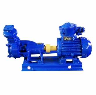
Vortex pumps VK, VKS, VKO
- Series description
- Technical characteristics
- Downloads
- Related content
- Vortex
- Nuclear power
- Shipbuilding
- Metallurgy, mining
- Water supply
- Water supply
- Water supply
- Clear water
- Sea water
Function
Vortex pumps of VK, VKS, VKO and electric pump units on their base are intended for pumping water and other liquids similar to water in viscosity – up to 36*10-6 m²/s (36 sSt) and in chemical activity, with content of solids not more than 0,01% by weight and the size of particles not more than 0,05mm, in which the materials of flow passage not permit linear speed of continuous corrosion more than 0,1 mm/year as per GOST 9.908-85.
On the base of the material of the main flow passage components the pumps are manufactured in the following versions:
- VK – version А (cast iron), B (bronze), К (stainless steel)
- VKS – version A,B,K
- VKO– version А
Temperature of the pumped liquid for the pumps (units):
- version А – from 258 up to 358 К (from minus 15 up to +85°С)
- version B and K – from 233 up to 358 К (from minus 40 up to plus 85°С)
Vortex pumps of VK, VKS, VKO type and electric pump units on their base are manufactured for National economy needs. Vortex pumps of VK, VKS type and electric pump units on their base may be installed on the marine ships with unlimited region of navigation having navigation class of Russian Maritime Register of Shipping (RMRS) and on the ships of home navigation and dual navigation (river-sea) having navigation class of Russian River Register (RRR). Units may be installed in the boiler and engine rooms of the ships having an automation industrial mark А1 and А2 within the RMRS classification of ships.
Pumps are related to the items of aspect 1 (repairable ones) as per GOST 27.003-90 and are manufactured in climatic version U3.1, U2 and ОМ2 as per GOST 15150-69.
Pumps and units are designed subject to safety requirements defined by GOST R 52743-2007.
Pumps are manufactured with the shaft gland sealing and do not provide pumping of flammable, harmful and highly-inflammable liquids.
Design
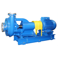
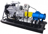
Electric pump unit consists of the pump and driving motor, mounted on the common foundation frame or plate and interconnected by elastic coupling.
VK, VKS, VKO pumps – are vortex, single-stage, horizontal, cantilevered.
The impeller which is a disk with radially positioned blades moves the liquid along the ring channel giving it the necessary energy.
Dimensions of the hydraulic part of the pumps are changed according to their standard size, but their construction is the same. The working chamber of the pump flow passage is executed in the casing and casing cover, and is a ring channel connected with the inlet and outlet pump nozzles. The suction and delivery parts of the channel are divided by a bridge (cutter-off).
The impeller is keyed on the shaft and has the possibility of free movement in the axial direction. Holes in the disk unload the impeller off the axial forces.
The pump shaft rotates in two ball bearing supports, positioned in the pump bracket.
To reduce leaks of the pumped product into the surroundings provision is made in the pump casing for the stuffing box.
To ensure self-suction, the VKS pumps are equipped with delivery hood on the outlet nozzle.
In VKO pumps the heating cover with the cover and the heating disk with the casing form the heating chamber, in which a vapour or cooling liquid is supplied.
The direction of rotor rotation has no matter for the pump and is defined only by the pipelines position and by precondition concerned with proper transfer of the liquid being pumped from the suction pipeline to the delivery pipeline along the big arc.
Application
- pumping of pure water and liquids similar to water in the sphere of housing and communal services and agriculture
- providing of water-supply in technological processes of industrial enterprises, the enterprises of heat and nuclear power, oil and gas branch, shipbuilding
Features /Advantages
- wide head range at small capacities
- linear relationship of head from capacity
- good self-priming ability
Technical parameters
| Pump models | Flow (nomin.), m³/h | Head, m | Pump power input (max.), kW | Rotation speed, rpm | Rotation speed, c˜¹ | Pump inlet pressure, kgf/sm², max | Pump efficiency,% | Pump unit efficiency,% | Voltage, V | Frequency, Hz | Type of current | Admissible positive suction head, m, max | Suction lift (max), m | Allowable duration of priming (max.), sec. |
| VK, VKS, VKO 1/16 | 3.4 | 16 | 1.2 | 1450 | 24 | 2.5 | 28 | 22 | 220/380/660 | 50/60 | AC | 4 | 4 | 600 |
| VK, VKS, VKO 2/26 | 3.6 | 26 | 4.6 | 1450 | 24 | 2.5 | 33 | 26 | 220/380/660 | 50/60 | AC | 5 | 4 | 600 |
| VK, VKS, VKO 4/28 | 14.4 | 28 | 7 | 1450 | 24 | 2.5 | 41 | 32 | 220/380/660 | 50/60 | AC | 6 | 4 | 600 |
| VK, VKS, VKO 5/24 | 18 | 24 | 8.3 | 1450 | 24 | 2.5 | 38 | 30 | 220/380/660 | 50/60 | AC | 6 | 4 | 600 |
| VK, VKS, VKO 5/32 | 18 | 32 | 8.8 | 1450 | 24 | 2.5 | 39 | 30 | 220/380/660 | 50/60 | AC | 6.5 | 3.5 | 600 |
| VK, VKS, VKO 10/45 | 36 | 45 | 27 | 1450 | 24 | 2.5 | 35 | 31 | 220/380/660 | 50/60 | AC | 7 | 3 | 600 |
Pump type key
For example VKО 2/26 А – U3.1 ТU 26-06-1213-81, where:
- VK - type of the pump : VK – vortex cantilevered, VKS – vortex cantilevered self-priming, VKO – vortex cantilevered heated (cooled)
- 2 - capacity, l/s
- 26 - head, m
- А - conventional designation of the flow passage material: А - cast iron, B- bronze, К - stainless
- U3.1 (or U2, ОМ2) –climatic version and location category
Instruction manual :
All technical documentation in the Russian version of the site »
Certificates, permits :
All certificates, permits in the Russian version of the site »
Order forms :
-
Download
(19.07.2013 / 54.5 Kb / doc)
© Copyright 1999-2020. All rights reserved. When using materials from the site and permit the direct hyperlink on www.hms-livgidromash.com reserved.
231, Mira Street, Livny town, Orel region, Russian Federation, 303851

