| Sale of pumps: | sbyt@hms-livgidromash.ru |
|
Reception: |
lgm@hms-livgidromash.ru |
- Homepage
- About company
- Products
- Pumps by TYPE
- Pumps by APPLICATION
- Water and utilities
- Oil and Gas
- Thermal power
- Nuclear power
- Chemical processing
- Shipbuilding
- Metallurgy, mining
- Food industry
- Firefighting
- Household
- Pumps by PUMPED FLUIDS
- Pumping EQUIPMENT
- Sales
- Service
- Press center
latest news :29.11.19
- Contacts
- Products
- »
- Catalog
- »
- Pumps by TYPE
- »
- Overhung
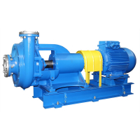
Centrifugal overhung close-coupled electric pumps KM
- Series description
- Technical characteristics
- Downloads
- Related content
- Overhung
- Close coupled
Function
Centrifugal cantilevered single-block electric pumps of KM type are intended for pumping service water under steady-state conditions (with exception of sea water) with рН=6 – 9, containing mechanical admixtures not more than 0,1 % by weight and the size of particle of 0,2 mm maximum, as well as the other liquids similar to water in density and chemical activity having a temperature of minus 10 up to + 85 ºС.
Electric shock protection class I GOST 12.2.007.0-75. Electric pumps are related to the items of aspect I (repairable ones) as per GOST 27.003-90. Climatic version У, location category 3.1 as per GOST 15150-69. Electric pumps are not intended for installation in explosion and-fire hazard premises.
Design
The electric pump consists of the centrifugal pump and flanged electric motor with elongated shaft end. The sense of shaft rotation – clockwise as viewed from the electric motor end. The arrow indicating the direction of rotation is arranged on the pump casing.
The casing of the pump is a iron casing in which the inlet and outlet branches, spiral chamber and supporting legs are executed. The casing of the pump is connected to the electric motor by the connecting piece.
The impeller is an iron casting and is secured on the shaft by using the key and screw or by the nut.
The sealing of the shaft – is a single soft stuffing box. To prevent a wear of the shaft there is a protection sleeve just under the stuffing box.
Application
- pumping of pure water (cold, hot up to 105°C) in water supply systems in complexes of housing and communal services, municipal water canals
- ensuring additional circulation in water and heat supply systems - of apartments and economic objects
- supply systems of service water, for technological processes of industrial enterprises including oil refining and metallurgical branches
- providing with water of gardening suburbs
- fire extinguishing systems of inhabited and civil objects
- heat and power engineering objects, for work of the main and auxiliary systems of stations which are connected with use of pure and service water
Features /Advantages
- own supporting enable pump dismantling without disconnection from pipelines
- compact design
- no need of unit alignment and as a result lower vibration and noise levels
Technical parameters
| Pump models | Flow (nomin.), m³/h | Head, m | Rotation speed, rpm | Rotation speed, c˜¹ | Pump inlet pressure, kgf/sm², max | Pump efficiency,% | Voltage, V | Frequency, Hz | Type of current | Admissible positive suction head, m, max | Engine power, kW |
| KM 50-32-125 | 12.5 | 20 | 2900 | 48 | 3.5 | 58 | 380 | 50 | AC | 3.5 | 2.2 |
| KM 50-32-125a | 10 | 16 | 2900 | 48 | 3.5 | 56 | 380 | 50 | AC | 3.5 | 1.5 |
| KM 65-50-125 | 25 | 20 | 2900 | 48 | 3.5 | 66 | 380 | 50 | AC | 3.8 | 4 |
| KM 65-50-125a | 23 | 16 | 2900 | 48 | 3.5 | 64 | 380 | 50 | AC | 3.8 | 4 |
| KM 65-50-160 | 25 | 32 | 2900 | 48 | 3.5 | 62 | 380 | 50 | AC | 3.8 | 5.5 |
| KM 65-50-160a | 20 | 25 | 2900 | 48 | 3.5 | 59 | 380 | 50 | AC | 3.8 | 4 |
| KM 80-65-160 | 50 | 32 | 2900 | 48 | 6 | 71 | 380 | 50 | AC | 4 | 7.5 |
| KM 80-65-160a | 45 | 28 | 2900 | 48 | 6 | 69 | 380 | 50 | AC | 4 | 7 |
| KM 80-65-160b | 40 | 20 | 2900 | 48 | 6 | 66 | 380 | 50 | AC | 4 | 5.5 |
| KM 80-50-200 | 50 | 50 | 2900 | 48 | 6 | 66 | 380 | 50 | AC | 4.5 | 15 |
| KM 80-50-200a | 45 | 40 | 2900 | 48 | 6 | 62 | 380 | 50 | AC | 4.5 | 11 |
| KM 100-65-200 | 100 | 50 | 2900 | 48 | 6 | 73 | 380 | 50 | AC | 4.5 | 30 |
| KM 100-65-200a | 90 | 40 | 2900 | 48 | 6 | 66 | 380 | 50 | AC | 4.5 | 22 |
| KM 100-65-250 | 100 | 80 | 2900 | 48 | 6 | 68 | 380 | 50 | AC | 4.5 | 45 |
| KM 100-65-250a | 90 | 67 | 2900 | 48 | 6 | 64 | 380 | 50 | AC | 4.5 | 37 |
| KM 100-80-160 | 100 | 32 | 2900 | 48 | 6 | 76 | 380 | 50 | AC | 4.5 | 12 |
| KM 100-80-160a | 90 | 26 | 2900 | 48 | 6 | 71 | 380 | 50 | AC | 4.5 | 11 |
| KM 100-80-160b | 80 | 20 | 2900 | 48 | 6 | 71 | 380 | 50 | AC | 4.5 | 7 |
| KM 150-125-250 | 200 | 20 | 1450 | 24 | 6 | 82 | 380 | 50 | AC | 4.2 | 18.5 |
| KM 150-125-250a | 180 | 16 | 1450 | 24 | 6 | 81 | 380 | 50 | AC | 4.2 | 15 |
Pump type key
For example KM50-32-125a-t-U3.1 TU3631-216-05747979-2003, where:
- КM – cantilevered close coupled pump
- 50 – diameter of inlet nozzle, mm
- 32 – diameter of outlet nozzle, mm
- 125 –nominal diameter of impeller, mm
- а – index number of impeller turning: a, b, v – reduced impeller diameter
- t – type of the seal: 5 or t – end seal of the shaft, c – gland seal of the shaft
- U – climatic version
- 3.1 – location category
Instruction manual :
All technical documentation in the Russian version of the site »
Certificates, permits :
All certificates, permits in the Russian version of the site »
Order forms :
-
Download
(19.07.2013 / 54.5 Kb / doc)
© Copyright 1999-2020. All rights reserved. When using materials from the site and permit the direct hyperlink on www.hms-livgidromash.com reserved.
231, Mira Street, Livny town, Orel region, Russian Federation, 303851

