PRODUCTION AND SALE
| Sale of pumps: | sbyt@hms-livgidromash.ru |
|
Reception: |
lgm@hms-livgidromash.ru |
- Homepage
- About company
- Products
- Sales
- Service
- Press center
latest news :29.11.19
- Contacts


")


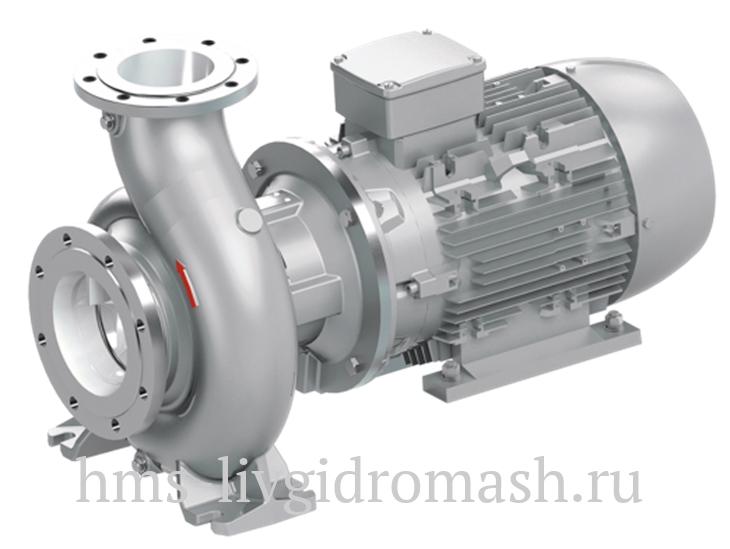
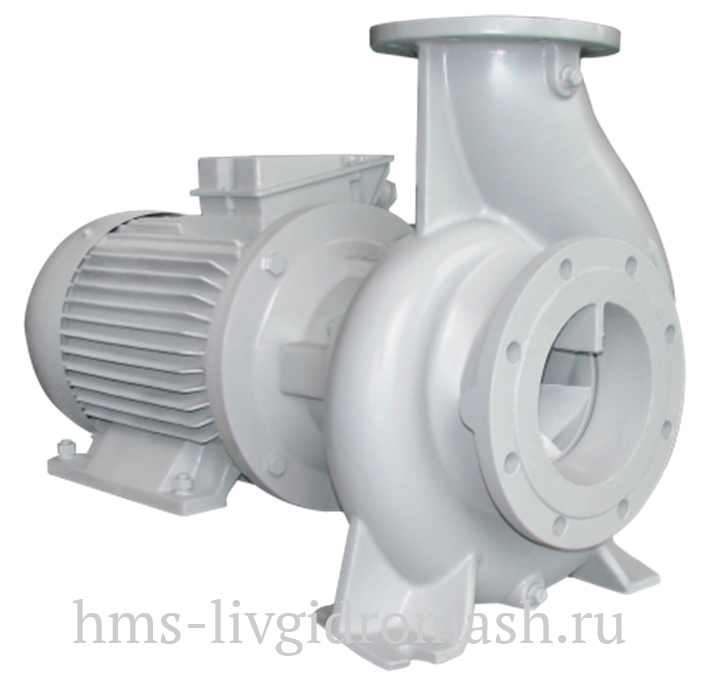
Kordis pumps: cantilevered and close-coupled cantilevered for water supply engineering
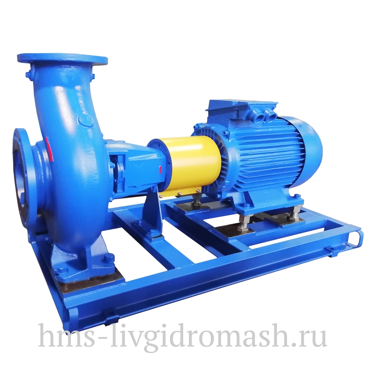

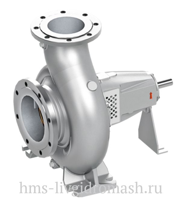


- Overhung
- Close coupled
Function
«Kordis» pumps - are the centrifugal machines:
- cantilevered pumps – are listed as pumps of K type,
- close-coupled cantilevered pumps – are listed as pumps of КМ type,
- close-coupled cantilevered pumps with in-line branch pipes - are listed as pumps of KL type
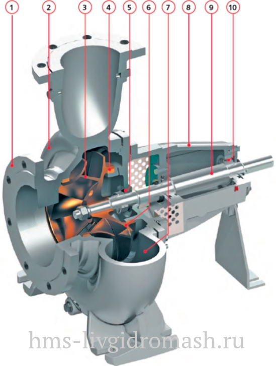
Design

Application
- facilities for supply and recirculation of service water
- fire-fighting water distribution systems of ring-type
- integral systems for water & heat supply of the administration and amenity buildings and utilities
- facilities for discharge of purified wastewater
Features /Advantages

|

|

|

|

|
1. Flanges can be fabricated in compliance with the standards GOST, ISO, DIN, ASME;
The construction design of the branch pipes and flanges is rated at working pressure of up to 25 kgf /сm2 for the pumps of cantilevered and close-coupled modification, and up to 16 kgf /сm2 for the pumps of cantilevered, close-coupled modification of in-line arrangement of branch pipes.
2. Significant range of available standard sizes of the pump and technical feasibility of impeller cutting allow us to select the pump in a strict correspondence with technical requirements of the hydraulic system of the Customer.
3. Dynamically balanced impeller of closed type ensure low values of vibroactivity of the pump rotor: thus reducing service costs and saving the energy.
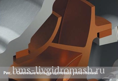
4. The replaceable rings of groove seals made out of up-to-date wear-resistant materials with special anti-scratch coating make it possible to diminish dynamic loads onto the rotor and pump supports and to prolong the service lifetime of the bearings and seals (Fig. 1).
5. The seal chamber allows to accommodate not only gland seals but also single end-face seals including those ones of the cartridge type (Fig. 2).
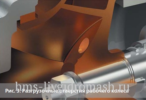
6. Impeller has been relieved against axial forces with the help of special relief holes on the rear disk of the impeller in order to decrease the load applied onto the bearings and to extend their service life (Fig. 3).
7. Energy-effective hydraulics of the flow passage has been optimized thanks to modern computer-aided design methods: thus ensuring high level of efficiency.
8. The construction design of the pump which provides for the removable rotor portion and detachable bracket of the bearing unit, make it possible to perform technical maintenance without dismantling the pump casing and inlet pipelines.
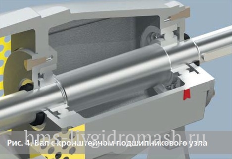
9. The shaft of rigid construction with enhanced bending strength ensure minimum values of vibration and run-out for the purpose of extending the life of the seal and bearings (Fig. 4).
10. Standard or reinforced (with service life of 100 000 hours minimum) bearings with lubrication in oil vat, including the cooling system (as an option).
The high level of unification of the main subunits of the pumps of various standard sizes and modifications significantly simplifies their technical maintenance.
The wide range of material versions allows application of the pumps for different media, including aggressive ones.
Technical parameters
Pump type key
For example: K - (-N) - 150 - 125 – 250 (-.1) / 269 – 220 / 4 – XXX , where:
-
К – is the type of the pump:
К - is the horizontal, cantilevered pump with casing mounted support
КМ – is the horizontal close-coupled cantilevered pump with casing mounted support
KL – is the vertical close-coupled cantilevered pump with in-line branch pipes
- (-N) – aggregated modification
- 150 – Nominal (DN) diameter of the suction branch pipe (DN)
- 125 – Nominal (DN) diameter of the delivery branch pipe (DN)
- 250 – Nominal (DN) diameter of the impeller (mm)
- (-.1) – reduced capacity
- 269 – Actual diameter of the impeller (mm)
- 220 – Rated power of the motor (кW х 10)
- 4 – Number of motor poles
- ХХХ – Design (embodiment)
Instruction manual :
All technical documentation in the Russian version of the site »
Certificates, permits :
All certificates, permits in the Russian version of the site »